Thursday, September 30, 2010

Fan Assisted Floor Tiles


If sub-floor pressure is the factor for a cabinet overheating but it can not be relocated, there is a solution available. Smart fan assisted cooling can help remedy this issue. If the CRAC unit can not blow the cold air to the perforated tile, then draw it there with smart fan tiles that mount below the perforated tile.

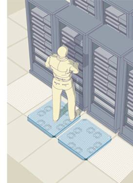
Smart fan-assisted floor tiles utilize a temperature probe that is mounted in the target cabinet. This probe has set thresholds that act as a thermostat for the fan tile. The fan ramps up speed as the requirement increases. As the requirement decreases the fan will return to an idle speed.

It is critical to make sure that there is enough cooling capacity to support the data center load, otherwise fan tiles will only relocate the hot spot. It is also important to know that fans require power and therefore produce heat which is why you should install a variable speed fan tile that ramps up fan speed only when it is required.

The figure below illustrates how the fan assisted floor tile extracts the air from the sub-floor no matter what the sub-floor pressure is. The results (purple plume) are dramatic compared to the (yellow plume) passive perforated tile next to it.

Intelligent air movers for the exhaust air are also available. Much like the floor tile, the ducted fan utilizes a temperature probe to control fan speed. The air mover is placed above the suspended ceiling. 12” flex duct is routed from a ceiling vent placed above a hot spot, to the unit, and exhaust from a ceiling vent placed above a CRAC unit.

To learn more, click here.

Wednesday, September 22, 2010

NER National Sales Meeting

NER Data Corporation will be holding it's annual National Sales Meeting Sunday 9/26 thru Tuesday 9/28. Our entire team of field sales representatives will be in attendence. As a result, there may be a short delay in answering your voicemails and emails.

If you have immediate needs or questions, please contact our inside support team.


Technical Support
TSSupport@nerdata.com

Custome Service
TSPurchasing@nerdata.com

We want to thank you in advance for your patience!

Tuesday, September 21, 2010

Using Floor Tiles with Increased Perforation


Servers and other racked equipment are more than capable of cooling themselves with onboard fans. This equipment has a three part set of cooling specifications requiring the data center to supply.

- The first is air temperature typically between 65˚F and 80˚F.
- 30%-60% relative humidity (some experts prefer the higher air density that 60% RH has to offer however, there is a higher energy consumption associated with the production of humidity).
- CFM: 1 kW equals 120CFM to maintain a 20˚F delta through the device.

The percentage of perforation of the floor tile in conjunction with the sub-floor air pressure will dictate the amount of air that can flow through it. Increasing the percentage of perforation can increase the amount of air that the tile can flow, so why not replace all of the perforated floor tiles with 56% perforated grates? The answer; the sub-floor pressure may drop to the point where air delivery in sections of the data centers will depreciate greatly.

In the model below the top pane uses a single 56% perforated tile. The flow is increased through the 56% perforated tiles relatively. In the lower pane all of the perforated tiles are 56% perforated. The air flow varies greatly due to a drop in sub-floor pressure.

The key here is moderation. Place the higher perforated tiled in front of the higher density enclosures which require them. As mentioned above, 120cfm of air will maintain a 20˚F delta for a 1kW load. How can you tell if you are doing it right?

1. Measure the electrical load of the enclosure you are trying to cool. This can be done by multiplying the current reading on the power strip meters by the voltage of the power in the strips. Example: 22amps x 208volts= 4,576watts or 4.576kW.

2. Now multiply the 4.567kW by 120cfm = 548cfm of air required

3. Now you will need to use a tool called a “Flow Hood Balometer”. This flow hood has a 2’x2’ square box that fits over the 2’x2’ perforated floor tile. Inside the flow hood box is a meter that measures the amount of air flowing through it. These flow hood may be able to be rented from your local rental facility otherwise they rage from $800-$3000 new.

4. Adjust the percentage of perforation to match the airflow requirement as closely as possible. Some perforated floor tiles have an adjustable baffle that you can use to change the airflow of the tile.

5. Let the tile sit for about 20-30 minutes and return to take temperature readings at the front top, middle, and bottom of the cabinet. If any of the temperatures exceed 80˚F you may have to increase the cfm of air flow through the tile. You may also need to correct some in-efficiencies discussed further in this document.

6. Another option is to have a data center professional conduct a Computational Fluid Dynamic (CFD) study on your data center which can provide all of this information.

Interview in Lyra's The Hard Copy Observer

NER's Steve Oatway, President / COO and Scott Steele Scott Steele, Senior Vice President of Business Development recently sat down to talk more about the firm’s transformation and plans for the future.

Download the entire interview here.

Tuesday, September 7, 2010

Sub-Floor Air Flow & Redundancy


The sub-floor of a data center is very similar to a weather system. There are mountains and valleys in the form of sub-floor congestion and opposing fronts coming from multiple CRAC units. All of these factors together create high and low pressure areas. It is imperative to know where these areas exist under the floor because will affect the air delivered to your cabinets.

As CRAC units come on and off line, high and low pressure areas change. Vortexes that resemble hurricanes are common under the subfloor. You do not want your high density cabinet placed in the eye of that storm. Air delivery will be little or reversed. Air can be drawn under the floor from above. The CFD modeling can predict the locations of the high and low pressure areas under all of the redundant CRAC scenarios.

The figure below illustrates how the air plume thru the perforated tile decreases as it nears the center of the sub-floor vortex.